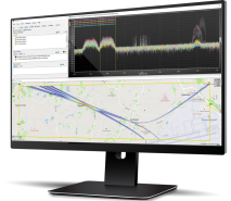
RFeye Site software at a glance
For nearly 20 years, spectrum managers, SIGINT officers and regulators have relied on RFeye Site. It provides all the essential functionality needed for full spectrum operations, turning spectrum data into RF intelligence. In real-time, users can carry out RF spectrum sweeps, I/Q capture, measurements of power, occupancy, bandwidth and frequency deviation; and visualization via interactive charts, maps and graphs.
This spectrum monitoring software and geolocation toolkit is packed with advanced functionalities ideal for RF experts. Multi-mission capability enables multiple spectrum monitoring and geolocation tasks to be run simultaneously. The software can also be customised to your application requirements and includes optional plugins.
The software now includes an advanced feature—Signal Discovery for RFeye Site. Designed to find and geolocate hidden radio frequency (RF) signals in real-time, operators now need no prior knowledge of a signal’s parameters to find it.
- Signal Discovery tool to reduce the cognitive load
- ITU compliant measurements & evaluation
- Comprehensive analysis & informative reports
- Advanced geolocation (inc 3D TDoA)
- Sophisticated simulation tool
- Discover hard-to-detect signals
Multi-mission, multi-domain and multi-user
Connect to and task RFeye hardware with multiple missions simultaneously. Run multiple missions (geolocation, detection, measurement missions etc) in parallel for maximum flexibility.
Spectrum monitoring & measurements
Conduct ITU-compliant spectrum monitoring and all essential measurements including channel occupancy, power, and frequency deviation. Overlay and analyze with customizable charts and measurement tools.
Signal Discovery
Signal Discovery increases probability of intercept for hard-to-find, unknown signals, or signals hidden in the noise. It is especially useful to discover non-standard signals, drone telemetry and datalinks, and mesh modems, which help identify mesh networks.
Fast, accurate geolocation
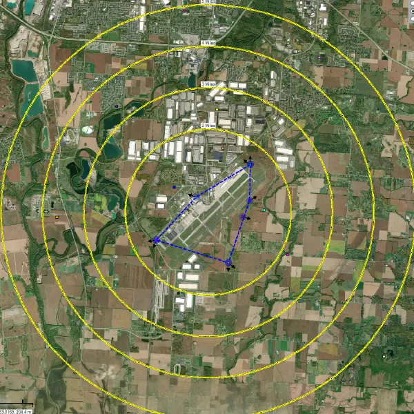
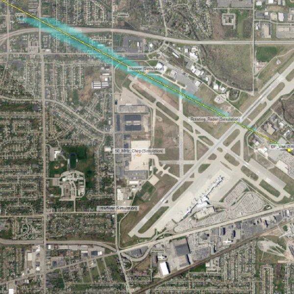
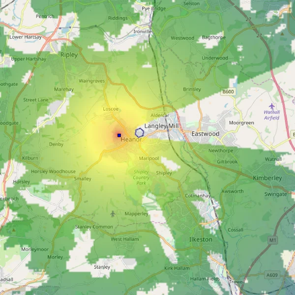
Manually or automatically detect signals of interest and geolocate the source by using multiple geolocation techniques. Time Difference Of Arrival (TDoA), Power On Arrival (PoA), Angle Of Arrival (AoA) techniques are all supported as well as hybrid geolocation which combines all of them, displayed within the interactive map.
Geolocate multiple targets over wide areas in real-time with extremely fast update rates ensuring accurate geolocation of emissions even from fast-moving targets. Hybrid geolocation draws on powerful algorithms, fast and accurate synchronised techniques (AoA, TDoA and PoA) for advanced localization and geolocation.
The post-processing TDoA feature allows geolocation of recorded signals allowing, for example, post-event diagnosis of interference incidents. Geolocation scenarios can be conducted with the simulation tool enabling users to practice and fine-tune their geolocation and interference-hunting skills.

Instantly visualize spectrum
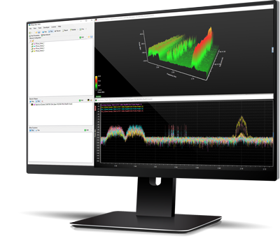
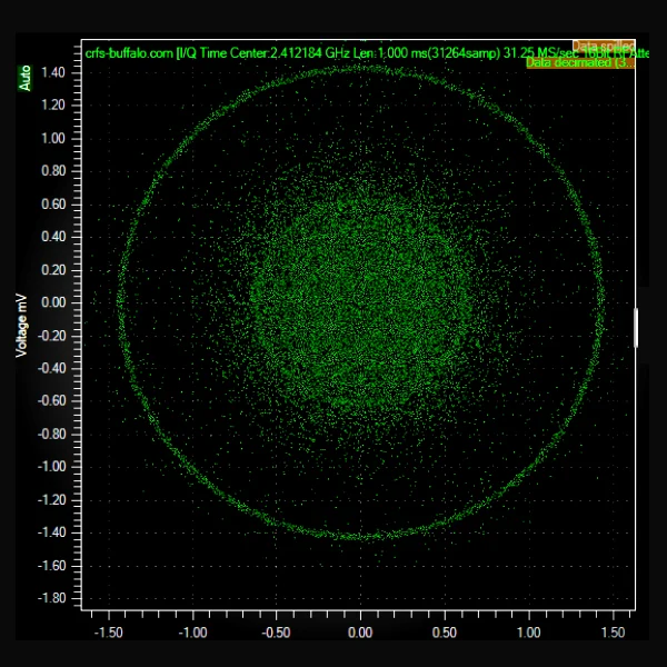
Fast and intuitive visualization of spectrum and signals of interest. This can be further enhanced by adding waterfall and I/Q data time charts.
Indoor geolocation
Detect and locate signals of interest for in-building applications (Technical Surveillance Counter Measures: TSCM). Use power masks, frequency exclusion bands, and geofencing to create trigger incidents or alarms when unauthorized surveillance devices are detected. These can be geolocated real-time based on the building floorplan.
Detector-based 3D TDoA
Airborne targets, including civilian and military drones and aircraft, have a range RF-emitting instruments. Operators can invoke signal detection missions specifically tuned for those signals. When the detector recognizes the signal triggers the 3D TDoA workflow to geolocate the moving aerial object. Passive surveillance and geolocation ensure the targets remain unaware they are being geolocated.
Training tool
Dynamic simulations with complete trainer control allows users to train from anywhere in any scenario. Replicate ‘red / blue’ force visibility, RF intelligence, and virtual or simulated sensors—creating terrain aware paths and tracks for transmitters to follow.
Powerful user interface
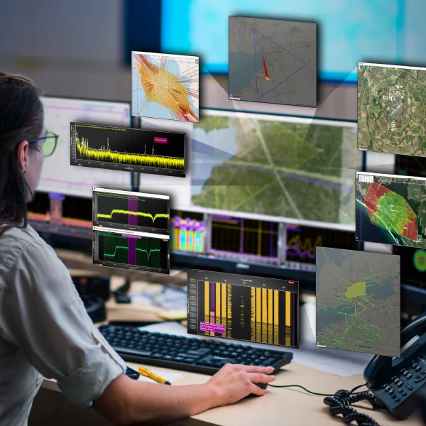
A unique floating frame design allows the user to create custom layouts for specific missions including control room visualizers. Once configured, the layout and all mission parameters can be saved as a ‘solution’ file—particularly useful when needing to respond quickly to changing situations.
For the best performance we recommend these specifications:
- CPU: Intel Core i9 or better
- Memory: 32 GB RAM or better
- Data storage: 1TB M.2 SSD or larger depending on I/Q data needs
- GPU: DirectX 11.0 compatible GPU with Shader Model 5 support and 256 MB VRAM
- Sound card: DirectX 9.0c compatible sound card
- Network: 1GB full duplex connection
- Screen resolution: 1920 x 1080 (CRFS recommends a minimum of two 32” displays)
- Thunderbolt interface for use with CRFS RFeye DeepView software system (optional)
RFeye support
Technical support
The customer support team can remotely assist with any issue, wherever you are located. Get practical help, receive answers to technical queries, access software workarounds, add more users, and enhance your software bundle by adding another CRFS software solution to your operation.
Training
CRFS provides on-site, remote, and classroom-style training for every skill level as well as bespoke set-up and training tailored to individual needs. For further information, browse the training modules available through Customer Support.
SSUS subscription
Software support and updates service (SSUS) provides permanent and continual access to CRFS support, new software features, and critical updates. Customers benefit from improved hardware and software performance, continued compatibility, and smoother integrations. SSUS information subscription ensures mission resilience.
Related Products
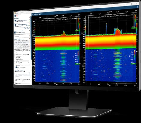
RFeye DeepView software
Observe the occurrence and properties of specific signals to gain situational awareness. Measure unknown or ‘unfriendly’ transmitters of interest (ToIs) and extract signal content by creating signal fragments or ‘snippets.’
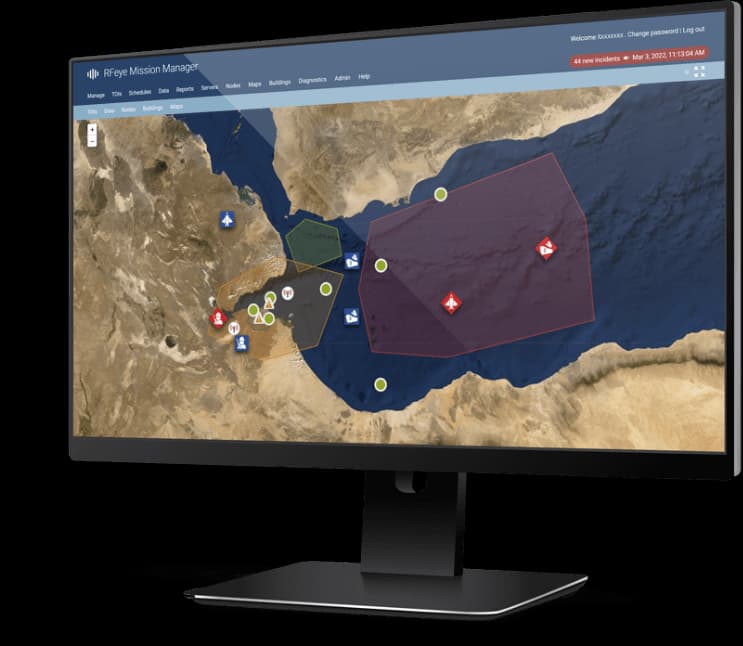
RFeye Mission Manager software
Mission Manager is a virtual spectrum manager, enabling users to establish and coordinate multiple scan operations, including sweep, occupancy, time, bearing, detector, and remote recording. Additionally, it permits sweep and interlinked surveys to form a command center from a central location. Software users can build a continuous and synchronous view of the spectrum as events happen.
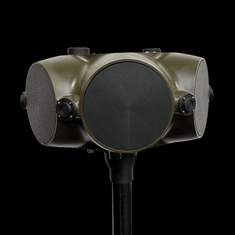
DFH40 | Compact DF Head Systems
The DFH40 Direction Finding antenna is a robust, field-ready solution for precision monitoring and direction finding from 500MHz to 40GHz, offering flexibility and frequency breadth across the SHF and lower EHF frequency bands. Designed for tactical deployments, the DFH40 enables reliable real-time direction finding, signal interception, and emitter geolocation where traditional systems cannot operate. Six high-performance spiral antennas with high-speed commutation and precise timing enable synchronized data correlation across multiple DF Heads and RFeye Nodes, delivering accurate geolocation of target signals using combined AoA and TDoA techniques. LOBs can be overlaid onto a wide variety of maps, satellite images and 2D / 3D GIS datasets, to give a unique positional display showing source geolocation probabilities. All signal types in the range can be mapped, irrespective of signal power, bandwidth or frequency. CRFS offers a selection of interchangeable DF Heads designed for use with Rapid Deployment Kits (RDKs), allowing users to build a toolkit suited to each mission.
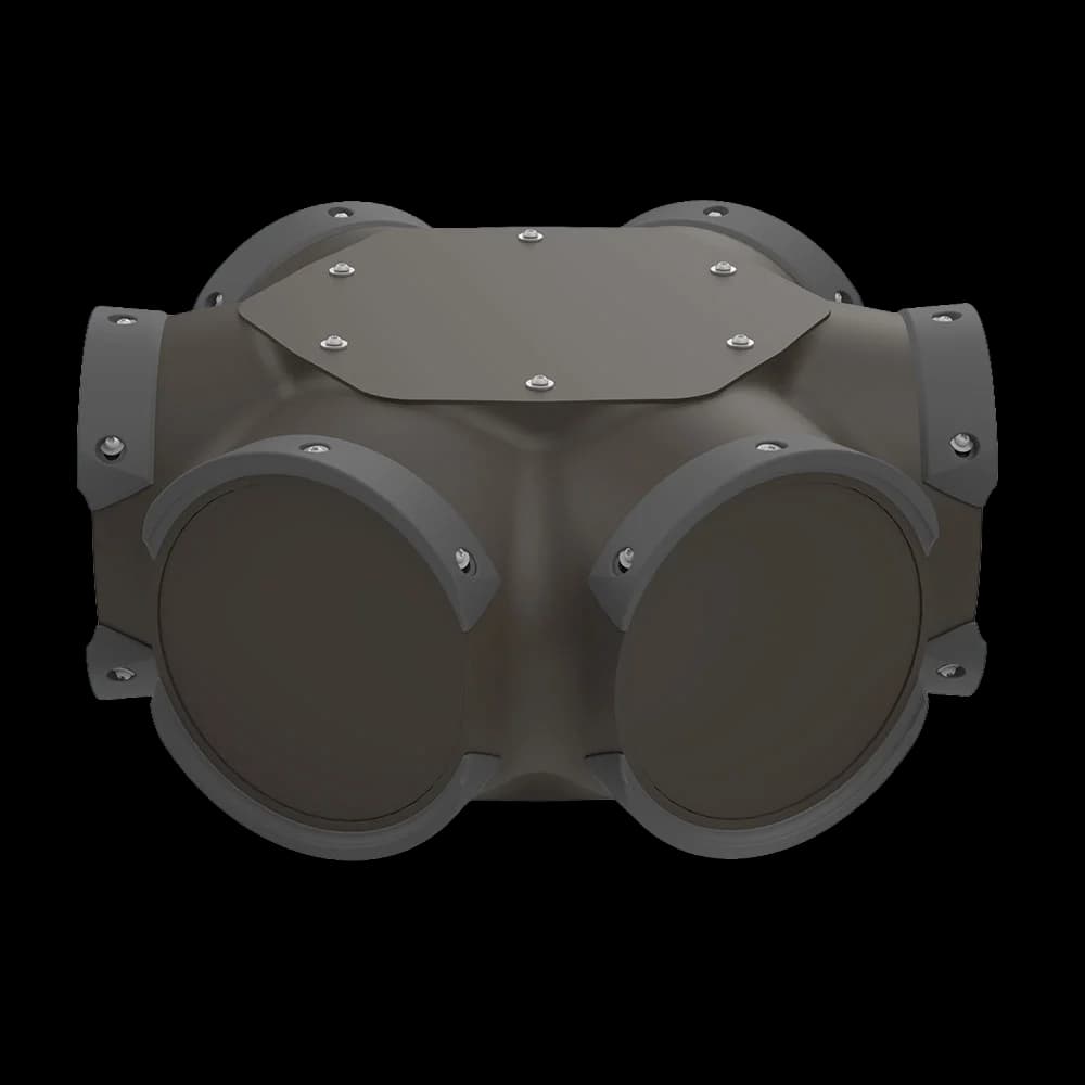
DFH18 | Compact DF Head Systems
The DFH18 Direction Finding antenna is a robust, field-ready solution for real-time 500MHz–18GHz line-of-bearing (LOB) with a typical DF accuracy of less than 2.5° RMS. It is compatible with the RFeye Node 100-18 and RFeye Node 100-40 and can be attached to any existing RFeye Node. Six high-performance spiral antennas with high-speed commutation and precise timing enable synchronized data correlation across multiple DF Heads and RFeye Nodes, delivering accurate geolocation of target signals using combined AoA and TDoA techniques. LOBs can be overlaid onto a wide variety of maps, satellite images, and 2D / 3D GIS datasets to give a unique positional display showing source geolocation probabilities. All signal types in the range can be mapped, irrespective of signal power, bandwidth, or frequency. Lightweight (7.5kg) and rapidly deployable, the DFH18 can be fully integrated into CRFS sensor networks and software ecosystems. Ideal for electromagnetic operations, border security, interference hunting, and wideband UHF/SHF/EHF COMINT/SIGINT operations. CRFS offers a selection of interchangeable DF Heads designed for use with Rapid Deployment Kits (RDKs), allowing users to build a toolkit suited to each mission.
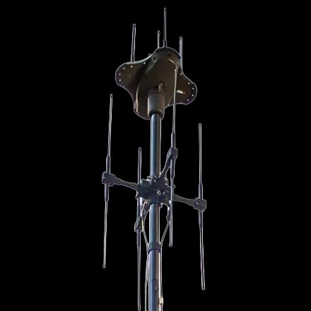
DFH500 | Compact DF Head Systems
The DFH500 Direction Finding antenna is a robust, field-ready solution for precision monitoring and direction finding from 30MHz to 500MHz, offering flexibility and frequency breadth across the VHF and lower UHF bands. Designed for tactical deployments, the DFH500 enables reliable real-time direction finding, signal interception, and emitter geolocation where traditional systems cannot operate. Lightweight and rapidly deployable, the DFH500 can be fully integrated into CRFS sensor networks and software ecosystems. Ideal for electromagnetic spectrum operations, border security, interference hunting, and VHF/UHF COMINT/SIGINT operations. CRFS offers a selection of interchangeable heads designed for use with Rapid Deployment Kits (RDKs), allowing users to build a toolkit suited to each mission.
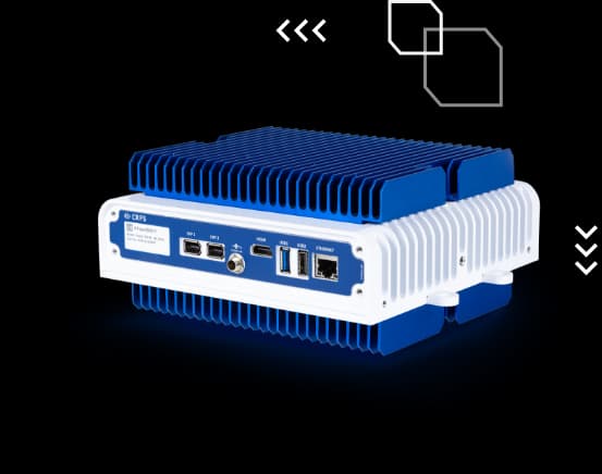
RFeye Node 100-40
The RFeye 100-40 is a high-performance RF sensor with a 9 kHz – 40 GHz frequency range and a 100 MHz instantaneous bandwidth. The RFeye Node 100-40 enables operators to monitor higher frequencies with advanced signal intercept by incorporating the latest superheterodyne receiver technology.
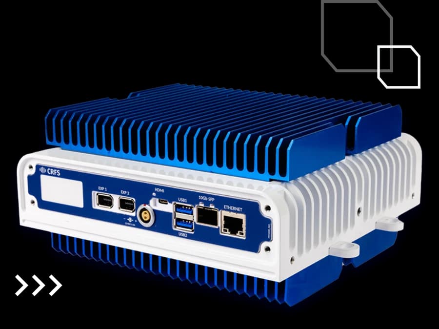
RFeye Node Plus 100-18
The RFeye Node Plus 100-18 is a high-performance spectrum analyzer and monitoring receiver designed for fast, long-distance data transfer via a 10 Gigabit Ethernet SFP+ port, supporting both fiber optic and copper connections. It covers a tuning range of 9 kHz to 18 GHz and features edge processing for full 100 MHz instantaneous bandwidth (IBW) recording, capture, and streaming. With a 120 dB dynamic range, 390 GHz/s sweep speed at 2 MHz RBW, and best-in-class frequency accuracy, tuning time, and phase noise performance, the sensor delivers exceptional RF sensing capabilities.
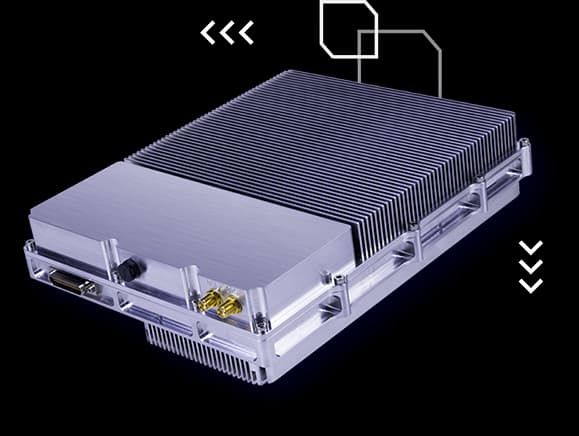
RFeye Lightweight Node 100-18-LW
The RFeye Node 100-18 LW (lightweight) sensor provides electronic warfare capabilities and RF intelligence in a compact, low Size, Weight, and Power (SWaP) package. Weighing 1.98 kg (excluding antennas), this intelligent RF sensor excels in signal detection, spectrum monitoring, and RF signal recording (I/Q data), capture, and geolocation up to 18 GHz.